Rig a Legged Robot
Learning Objectives
After completing this tutorial, you will have learned:
- How to set the initial pose to match a locomotion policy (a reinforcement-learning policy that controls walking/running)
- How to add the Joint State API and Angular Drive API to prepare joints for driving
- The meaning and configuration of joint settings — stiffness, damping, effort limit, armature, and maximum velocity
- How to enter USD values while being mindful of radian-to-degree unit conversion
- How to bulk-check joint properties with a Python verification script
Getting Started
Prerequisites
- Complete Tutorial 3: Articulate a Basic Robot
- Recommended: read Tutorial 11: Joint Drive Gain Tuning first, since stiffness/damping concepts will appear here
Assets Used
This tutorial uses the Unitree H1 humanoid sample asset bundled with Isaac Sim:
| File | Purpose |
|---|---|
Isaac/Robots/Unitree/H1/h1.usd |
Pre-rigging H1 (copy locally for editing) |
Isaac/Samples/Rigging/H1/h1_rigged.usd |
Reference asset that has already been rigged (use to verify the final state) |
The Samples folder is read-only, so copy h1.usd into a working folder before opening it. If you get stuck, open the reference asset h1_rigged.usd to compare against the expected configuration values.
Estimated Time
Approximately 20-30 minutes.
Overview
Unlike wheeled robots, legged robots have a constantly changing contact state with the ground, so they are commonly controlled by locomotion policies (neural networks for walking/running) learned via reinforcement learning. Because the policy is trained assuming a specific initial pose and specific joint characteristics, if the simulator settings do not match the policy specification, the robot will not walk properly.
In this tutorial, you will use the Unitree H1 humanoid robot as an example to learn how to rig a legged robot to match a locomotion policy's specification. The flow is as follows:
- Set the initial pose — match the joint angles expected by the policy
- Configure joint settings — enter the stiffness, damping, effort limits, and other values specified by the policy
- Verify with a script — read back the actual USD properties from Python to confirm the values
What is a locomotion policy?
Walking with a legged robot is a high-speed control problem of deciding "how much to move each joint at the next instant" every frame. Because designing this by hand is difficult, it is typically learned as a policy in a reinforcement-learning environment such as Isaac Lab. During training, the simulator settings — the robot's initial standing pose, PD gains, force limits, and so on — are fixed, and it is implicitly assumed that these still hold at inference time.
Radian vs. degree mismatch
Reinforcement-learning config files (Isaac Lab's env_cfg) describe joint angles, angular velocities, and gains in radians. USD joint properties, on the other hand, are in degrees. This unit conversion is the biggest pitfall during rigging, so this tutorial calls it out repeatedly.
| Quantity | Radian → degree conversion |
|---|---|
| Angle (target position) | ×180/π |
| Angular velocity (max velocity) | ×180/π |
| Stiffness | ×π/180 |
| Damping | ×π/180 |
Step 2 explains why stiffness and damping use the opposite direction of conversion.
Step 1: Set the Initial Pose
The H1 locomotion policy is trained from a slightly crouched stance, with the knees softly bent and the hip joints slightly pitched forward. Start by setting the target position of each joint to match this stance.
1-1. Open the Asset
- Create a working folder anywhere and copy
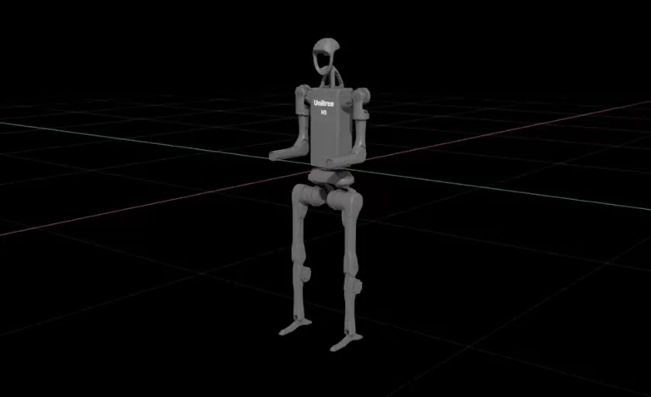
Isaac/Robots/Unitree/H1/h1.usdlocally. - Open the copied
h1.usdvia File > Open. - Confirm that H1 appears in the viewport in a "forward-reach" posture (both arms extended forward). This is the default pose before any locomotion-related rigging is applied — the joints have not yet been driven to their target positions.
Do not open the sample asset directly
The Samples area is read-only, so direct edits cannot be saved. Always start by copying the asset to a working folder.
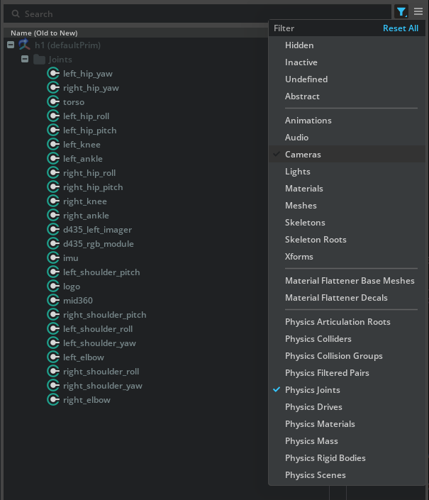
1-2. Filter Down to Joints
H1 contains many prims — links, joints, meshes, and so on. To make it easier to bulk-select joints, filter the Stage panel:
- Click the funnel (Filter) icon at the top right of the Stage panel
- From the menu, select Type Filters > Physics Joints
Now the Stage panel shows only joints (such as PhysicsRevoluteJoint).
1-3. Select All Joints and Add APIs
- Click the first joint in the list (for example,
left_hip_yaw) - Shift-click the last joint (for example,
right_elbow) to select every joint in between - With the selection active, right-click > Add > Physics > Joint State Angular
- Then right-click > Add > Physics > Angular Drive
This applies the following two APIs to every joint:
| API | Role |
|---|---|
| Joint State Angular API | Interface for reading each joint's current position and velocity. Used to supply observations to the policy. |
| Angular Drive API | Enables the PD controller that drives the joint toward its target position/velocity. |
Why the Joint State API is needed
A USD joint by itself represents only a physical connection — there is no standard external way to ask "what angle is this joint at right now?". Applying the Joint State Angular API exposes attributes such as state:angular:physics:position (position) and state:angular:physics:velocity (velocity), making them accessible to Python and to the policy as observations. Because a legged-robot policy observes joint states to decide its next action, this API is essential.
1-4. Enter the Target Position for Each Joint
The initial pose expected by the H1 locomotion policy is shown below (radian basis):
| Joint name (pattern) | Target position [rad] | Target position [deg] |
|---|---|---|
*_hip_yaw |
0.0 | 0.0 |
*_hip_roll |
0.0 | 0.0 |
*_hip_pitch |
-0.28 | ≈ -16.04 |
*_knee |
0.79 | ≈ 45.26 |
*_ankle |
-0.52 | ≈ -29.79 |
torso |
0.0 | 0.0 |
*_shoulder_pitch |
0.28 | ≈ 16.04 |
*_shoulder_roll |
0.0 | 0.0 |
*_shoulder_yaw |
0.0 | 0.0 |
*_elbow |
0.52 | ≈ 29.79 |
* means both sides (left_ / right_). All target velocities are 0.0.
Steps:
- In the Stage panel, select one joint to configure (for example,
left_hip_pitch) - In the Properties panel, open the Angular Drive section
- Enter the degree-converted value into Target Position (for example,
-0.28 × 180/π ≈ -16.04) - Set Target Velocity to 0.0
- Repeat for every joint
USD is in degrees; policy configs are in radians
Fields like env_cfg.scene.robot.init_state.joint_pos in Isaac Lab are in radians, but the USD Drive API expects degrees. Always pass values through × 180 / π before entering them. You can use Python as a calculator:
Batch-select symmetric joints
Joints that share the same value — like left_hip_pitch and right_hip_pitch — can be selected together with Ctrl + click, so that entering a value in the Properties panel applies it to all of them at once. This speeds up the work considerably.
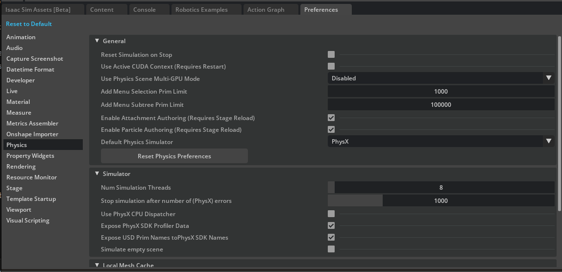
1-5. Preserve Values Across Simulation Reset
By default, Isaac Sim resets to the initial state when you press Stop, which can also wipe the Drive API target values. Disable that behavior:
- Open Edit > Preferences
- Select Physics in the left pane
- Uncheck Reset Simulation on Stop
The target positions you entered will now persist after Stop.
1-6. Verify the Initial Pose — Prevent Falling with a Fixed Joint
If you press Play as-is, H1 will collapse to the ground under gravity (it is not anchored anywhere yet). To visually verify the initial pose, temporarily fix the torso to the world with a Fixed Joint:
- Right-click
/h1/torso_linkin the Stage panel - Select Create > Physics > Joint > Fixed Joint
- Press Play in the viewport
You should see the robot stay upright while each joint converges to its target position (the slightly-bent-knee stance).
When you have confirmed the pose:
- Press Stop
- Delete the Fixed Joint you created (it is not needed for the rigged asset)
- Save with Ctrl + S
- (Optional) Re-enable Edit > Preferences > Physics > Reset Simulation on Stop
Why bother with a Fixed Joint?
H1 still lacks proper contact and friction settings on its feet. Pressing Play directly would cause it to fall or slip, making it impossible to tell whether it has converged to the target pose. Pinning the torso in mid-air with a Fixed Joint isolates the joint-drive behavior alone, so you can verify it visually.
Step 2: Configure Joint Settings
Now reflect the joint dynamics (PD gains, torque/velocity limits, armature, friction) that the policy assumed during training. Large mismatches here will break the policy.
2-1. H1 Actuator Specification
The representative values from H1's Isaac Lab config (scene.robot.actuators) used in this tutorial are shown below. Values entered into USD must be in degrees, so apply the conversion described in the next section before entering them.
Legs + torso (legs group)
| Joint | Stiffness [rad] | Damping [rad] |
|---|---|---|
*_hip_yaw |
150.0 | 5.0 |
*_hip_roll |
150.0 | 5.0 |
*_hip_pitch |
200.0 | 5.0 |
*_knee |
200.0 | 5.0 |
torso |
200.0 | 5.0 |
- Effort Limit: 300 N·m
- Velocity Limit: 100.0 rad/s
Arms (arms group)
| Joint | Stiffness [rad] | Damping [rad] |
|---|---|---|
*_shoulder_pitch |
40.0 | 10.0 |
*_shoulder_roll |
40.0 | 10.0 |
*_shoulder_yaw |
40.0 | 10.0 |
*_elbow |
40.0 | 10.0 |
Effort/velocity limits for the arms are often different from those for the legs, so always check the actual numbers in your policy's config file.
2-2. Unit-Conversion Points
USD stiffness/damping are defined as "torque produced per 1 degree of error / per 1 deg/s of error" — that is, on a degree basis. Isaac Lab is on a radian basis, so apply the following conversions:
| Quantity | Policy value [rad] | Value entered in USD [deg] |
|---|---|---|
| Stiffness | S_rad |
S_rad × π/180 |
| Damping | D_rad |
D_rad × π/180 |
| Max Joint Velocity | ω_rad [rad/s] |
ω_rad × 180/π [deg/s] |
| Effort Limit | unchanged [N·m] | unchanged [N·m] |
Why multiply stiffness by π/180?
PD-control torque is τ = K × Δθ. To produce the same torque when Δθ is expressed in degrees as it would with radians, K must be smaller (since 1 rad ≈ 57.3°). Specifically, S [N·m/rad] × 1 [rad] = S × (π/180) [N·m/deg] × 1 [deg], giving S_deg = S_rad × π/180. Damping uses × π/180 for the same reason. Conversely, when the velocity unit grows from rad/s to deg/s, the value increases by × 180/π.
For example:
- Hip pitch stiffness:
200.0 × π/180 ≈ 3.4907 - Hip pitch damping:
5.0 × π/180 ≈ 0.0873 - Max joint velocity:
100.0 × 180/π ≈ 5729.578
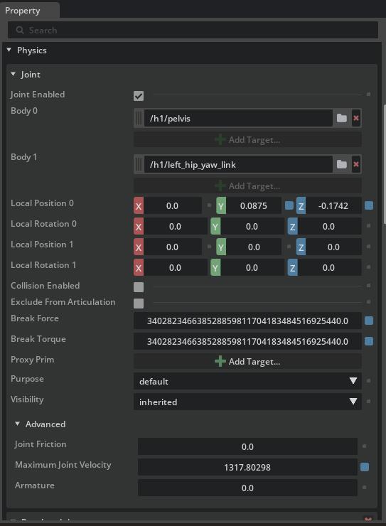
2-3. Entering the Properties
For each joint, set the following in the Properties panel:
- Select the joint (or a group of joints) in the Stage
- Angular Drive section:
- Stiffness =
S_rad × π/180 - Damping =
D_rad × π/180 - Max Force = effort limit (e.g., 300 N·m)
- Stiffness =
- Joint section:
- Maximum Joint Velocity =
ω_rad × 180/π(e.g., 5729.578)
- Maximum Joint Velocity =
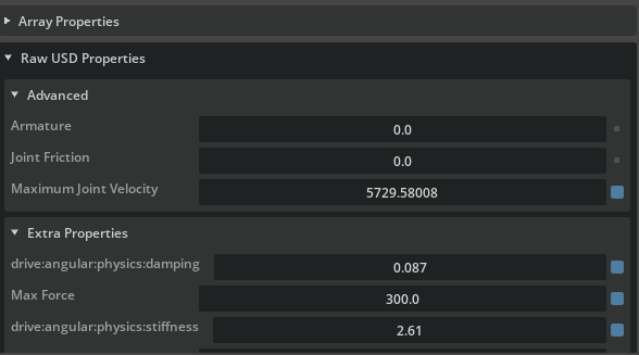
2-4. Armature and Friction (Raw USD Properties)
Armature represents the rotor inertia of a motor and is added to the joint's equivalent inertia for simulation stability. Joint friction is, as the name suggests, the friction torque at the joint. These properties may not appear in the default Properties view, so enter them under Raw USD Properties:
- Select the target joint
- In Properties, expand the Advanced group under the Physics > Joint section
- Set
Armatureto the policy value (for H1, 0.0 or unset) - Set
Joint Frictionto the policy value (for H1, 0.0 or unset)
H1 has zero armature and zero friction
The standard Isaac Lab H1 configuration leaves both armature and friction at 0 (equivalent to unset). Even if you do not enter values, default values will appear in dof_properties (confirmed in the next step). When working with a real robot, obtain the correct values from its datasheet or actuator specifications.
2-5. Save
Once all values are entered, press Ctrl + S to save.
Step 3: Verify the Joint Configuration
Checking values one-by-one in the GUI is tedious. Instead, use a Python script to dump every joint's properties at once and compare against the specification.
3-1. Open the Script Editor
- From the menu, select Window > Script Editor
- Paste the following script into the editor at the bottom:
from isaacsim.core.prims import SingleArticulation

prim_path = "/h1"
prim = SingleArticulation(prim_path=prim_path, name="h1")
print(prim.dof_names)
print(prim.dof_properties)
3-2. Running and Reading the Output
- Press Play to start the simulation (
SingleArticulationcannot read internal values until physics is initialized) - Run the script with the Run button in Script Editor (or Ctrl + Enter)
- Two outputs appear in the console at the bottom:
dof_names: list of joint names corresponding to the degrees of freedom (DOFs)-
dof_properties: an array of properties per DOF. Each row corresponds to one joint and the columns roughly mean:(type, hasLimits, lower, upper, drive_mode, maxVelocity, maxEffort, stiffness, damping)
3-3. Checklist
Check the output against the following:
-
dof_namescontains every H1 joint (hip / knee / ankle / torso / shoulder / elbow, both sides) - maxVelocity is
100.0for the legs (the degree-based USD value, converted back to radians internally) - maxEffort is
300.0for the legs - stiffness is
150.0forhip_yaw / hip_roll,200.0forhip_pitch / knee / torso, and40.0for the arms - damping is
5.0for the legs and10.0for the arms
Output is reported on a radian basis
dof_properties values are normalized back to a radian basis in the output. Even though you entered USD values in degrees, the numbers shown here can be directly compared to the policy config (Isaac Lab's env_cfg). If they do not match, the first thing to suspect is a unit-conversion mistake from Step 2-2.
Troubleshooting
| Symptom | Cause | Fix |
|---|---|---|
| Robot collapses when Play is pressed | Contact/friction not yet configured, and no Fixed Joint | Temporarily add a Fixed Joint to torso_link for pose verification, as in Step 1-6 |
| Joints settle at completely wrong positions | Stiffness/damping too small, or unit conversion missed | Verify the × π/180 conversion in Step 2-2 — errors compound quickly |
| Joints vibrate / oscillate | Stiffness too high, damping too low | Re-check the policy values — the actual policy numbers should be stable |
| Drive properties have no effect after entering values | Joint State / Drive API not applied to those joints | Reselect the joints in Stage and reapply Add > Physics > Angular Drive |
Error when creating SingleArticulation |
Simulation not running | Press Play before executing the Script Editor |
dof_properties values diverge from the spec |
deg ↔ rad conversion mistake, or values from the wrong group entered | Cross-check against the tables in Step 2-1, group by group |
| Target values reset when pressing Stop | Reset Simulation on Stop is ON | Turn it OFF in Edit > Preferences > Physics (at least while working through this tutorial) |
Summary
This tutorial covered the following topics:
- Setting the initial pose — adding Joint State / Angular Drive APIs and entering target positions after radian-to-degree conversion
- Pose verification with a Fixed Joint — temporarily pinning
torso_linkduring rigging to isolate drive behavior - Configuring joint settings — stiffness/damping (
× π/180), Max Force (unchanged), Maximum Joint Velocity (× 180/π), armature, and friction - Verification script — bulk-checking all joints via
SingleArticulation.dof_properties
H1 is a representative legged robot, but the workflow of "transcribe the policy specification's numbers into USD with unit conversions" is exactly the same for quadrupeds (ANYmal, A1, and so on) and other humanoids. Use this procedure as a template and substitute values for your robot or policy.
Reference asset for the final state
Isaac/Samples/Rigging/H1/h1_rigged.usd is the completed, rigged asset. Open it to compare how each value was entered and how the Raw USD Properties look.
Next Steps
This concludes the robot setup tutorial series. With the locomotion-rigging skills learned here, you can move on to training policies in Isaac Lab or deploying them on real hardware. Well done!