Asset Optimization
Learning Objectives
After completing this tutorial, you will have learned:
- How to restructure a robot asset for simulation (reparenting and layer setup)
- How to consolidate redundant mesh nodes with the Mesh Merge Tool
- How Scenegraph Instancing reduces memory usage and rendering cost
- Key checkpoints for performance — lights, materials, and colliders
- How to evaluate the effect by comparing frame rate (FPS) before and after optimization
Getting Started
Prerequisites
- Complete Tutorial 3: Articulate a Basic Robot
- Familiarity with USD composition concepts — sublayers, References, and Payloads (covered in Step 1 of Tutorial 10)
Assets Used
This tutorial uses the Jetbot sample asset bundled with Isaac Sim:
| File | Purpose |
|---|---|
Samples/Rigging/Jetbot/Jetbot_Base/Jetbot_base.usd |
Source asset (copy locally before use) |
Samples/Rigging/Jetbot/Jetbot_Optimized/Jetbot_optimized.usd |
Empty stage prepared for optimization work |
Samples/Rigging/Jetbot/Jetbot_Optimized/Jetbot_optimized_post_merge.usd |
Intermediate state after mesh merging (reference only) |
Samples/Rigging/Jetbot/Jetbot_Optimized/Jetbot_optimized_final.usd |
Final state after instancing (reference only) |
The three Jetbot_optimized*.usd files in the Samples folder are pre-optimized reference data. In this tutorial, you will copy Jetbot_base.usd into a working folder and create your own new Jetbot_optimized.usd to perform the optimization steps. If you get stuck, open the reference files above to compare with the expected state.
Estimated Time
Approximately 20-30 minutes.
Overview
Robot assets imported from CAD or other 3D software into Isaac Sim are often highly fragmented — meshes and materials split into many pieces. It is not unusual for a single wheel to consist of dozens of meshes and materials. While this looks fine visually, it bloats the scenegraph and degrades both rendering and physics performance.
In this tutorial, you will learn how to optimize a robot asset for simulation using the Jetbot robot as an example. The optimization improves performance from approximately 40 FPS to 64 FPS (about 1.6×) compared to the unoptimized state.
The flow is as follows:
- Restructure the asset — prepare layers and prim hierarchy for simulation
- Merge meshes — use the Mesh Merge Tool to consolidate each link to a single mesh
- Scenegraph instancing — share identical meshes as a single data source
- Other optimization checkpoints — lights, translucent materials, colliders, and more
Why does performance drop?
Every prim and mesh in the USD scenegraph adds its own draw-call and physics-evaluation overhead. Even if there are only 10 links, splitting them into 200 meshes results in roughly 200 draw calls. Mesh merging consolidates these into a single draw call, while instancing reduces memory by sharing identical data.
Recommended asset structure
The official Isaac Sim asset structure guidelines recommend organizing a robot asset into the following three stages:
| Stage | Contents |
|---|---|
| Asset Source (raw data) | Raw meshes and materials imported from CAD. Do not modify. |
| Transformation (optimized) | Asset with mesh merging and instancing applied. Created in this tutorial. |
| Features (feature layers) | Per-purpose layers for physics, sensors, ROS, and so on |
With this design, you can update the CAD by swapping out only Asset Source — you do not have to rebuild the rigging or physics setup.
Step 1: Restructure the Asset
First, prepare a new prim hierarchy for the optimized simulation asset. Without modifying the source asset (Jetbot_base.usd), you will build the optimized structure in a separate USD file (Jetbot_optimized.usd).
1-1. Enable Inherit Parent Transform
When you reparent meshes via drag-and-drop, changing the parent can shift the child's apparent position. To prevent this, enable inheritance of the parent transform during reparenting:
- Open Edit > Preferences
- From the list on the left, select Stage > Authoring
- Check Inherit Parent Transform
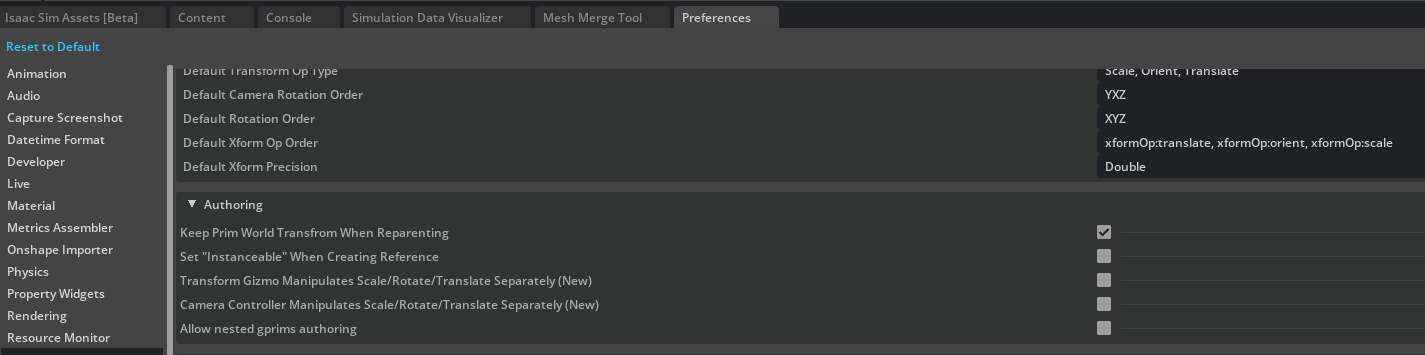
Why this setting matters
A USD prim's final world coordinate is computed as parent transform × local transform. With Inherit Parent Transform disabled, the parent transform is not inherited when the parent changes, so the world position can shift even if the local transform is unchanged. Since this optimization workflow moves many meshes between parents, enabling this once up front saves time.
1-2. Prepare a Working Folder and Copy the Asset
The sample assets are read-only, so first copy the base asset to a working folder (the same flow as Step 1-1 of Tutorial 10):
- Create a working folder somewhere convenient (for example, on the desktop, named
Jetbot_optimization) - In the Content tab, open
Samples/Rigging/Jetbot/Jetbot_Base/, then download theJetbot_base.usdfile along with any related resources in the same folder (such asMaterialsandparts, if present) into the working folder
You do not need to copy Jetbot_optimized*.usd
The files under Jetbot_Optimized are already pre-optimized reference data. You may open them to inspect the contents, but you do not need to copy them into your working folder.
1-3. Create a New Jetbot_optimized.usd and Insert the Sublayer
In the working folder, create a new USD file to hold the optimization results, and insert the base asset as a sublayer:
- Choose File > New to create an empty stage
- Choose File > Save As to save the stage as
Jetbot_optimized.usdinside the working folder you created in Step 1-2 - Open the Layer tab (if hidden, Window > Layer)
- With the Root Layer (
Jetbot_optimized.usd) selected, click the Insert Sublayer button - In the file dialog, select the
Jetbot_base.usdyou copied to the working folder
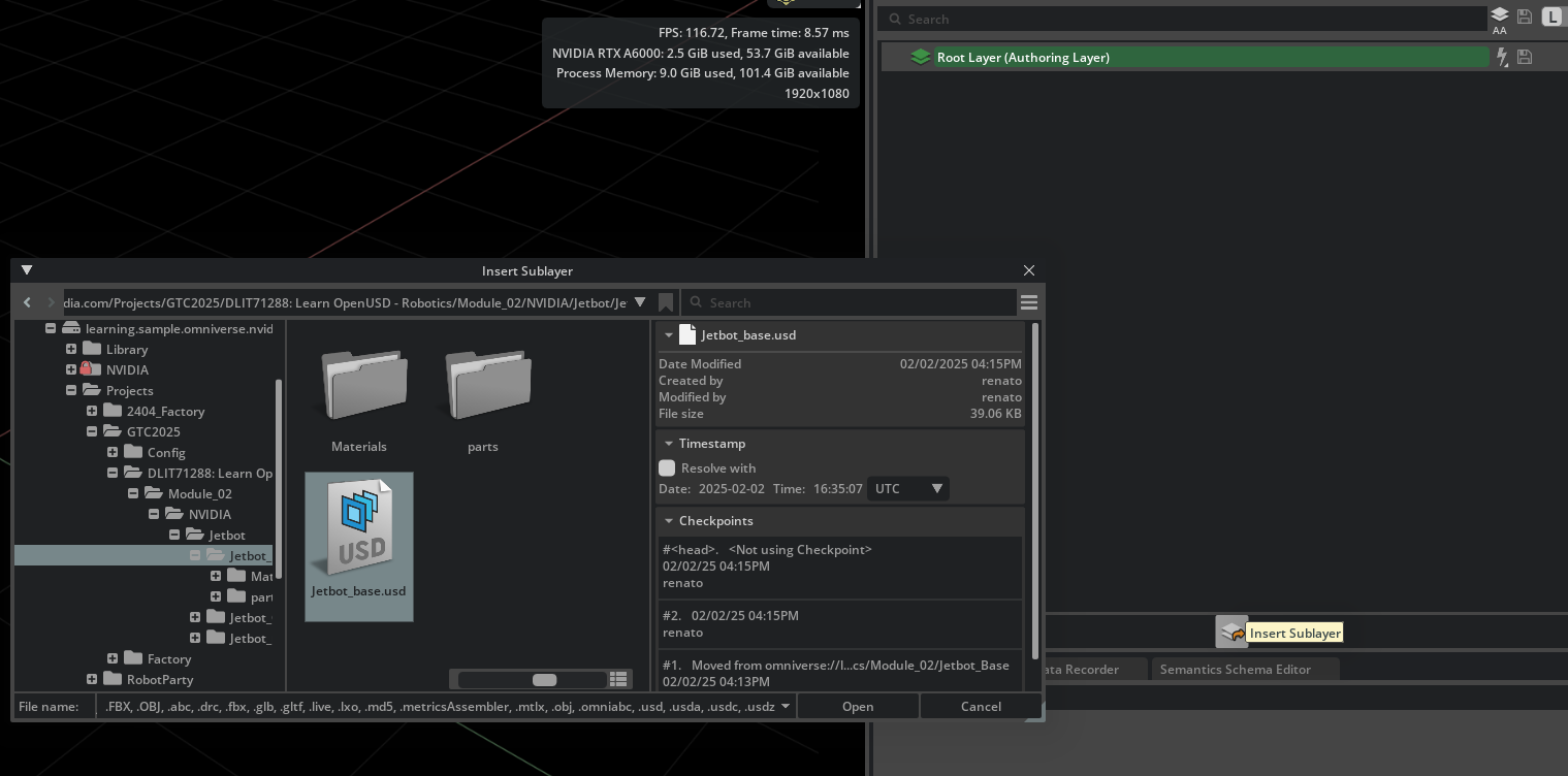
The Jetbot meshes and materials now appear in the viewport. Because Jetbot_optimized.usd is the Root Layer, all subsequent edits are recorded in this file, and Jetbot_base.usd itself is not modified.
You can sublayer directly from the Samples folder, but...
Technically, you can skip the local copy and sublayer the Samples-side Jetbot_base.usd directly. However, the Isaac Sim sample layout and paths can change between versions, so future asset lookups may break. Copying locally and referencing via a relative path improves reproducibility.
Sublayer vs Reference
As covered in Tutorial 10, a sublayer shares the same prim hierarchy and overrides properties on top of it, whereas a Reference / Payload places an external asset as an independent child prim. Here we want to keep the base asset's prim hierarchy and add an additional, parallel optimized Xform hierarchy alongside it, so a sublayer is the right fit.
Return to the Stage panel after working in the Layer tab
Once you have finished inserting the sublayer, all subsequent reparenting and prim creation happens in the Stage panel. The Layer tab is only for managing layers and switching the edit target — it is not where you select or edit prims directly. Trying to operate on prims from inside the Layer tab is a common way to get lost.
1-4. Create the Optimized Hierarchy
Create the Xform that holds the optimized asset:
- Right-click the Stage panel and choose Show Root to display the
/(root) level
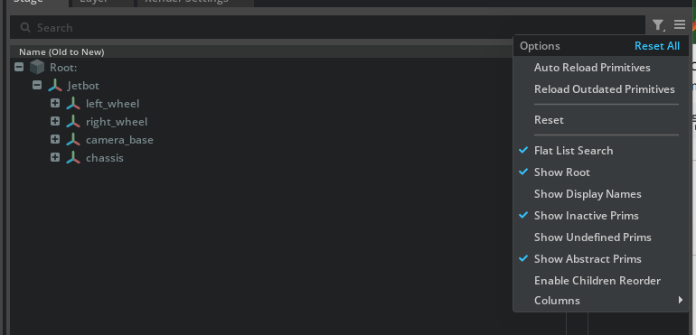
- Right-click the root and choose Create > Xform, then rename the new Xform to
Jetbot_Sim - Right-click
Jetbot_Simand choose Set as Default Prim (this becomes the asset's "front door") - Create another Scope directly under root and rename it to
Visuals(placing it outsideJetbot_Simis the key point)
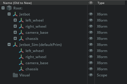
The Stage now has the following structure:
/
├── Jetbot_Sim       <- Default Prim (link hierarchy used for simulation)
├── Visuals          <- Holds visual meshes (used as instancing source)
└── Jetbot           <- Source asset (its contents will be moved out, leaving it empty)
Scope vs Xform
An Xform carries a coordinate transform and acts as a frame that applies position, rotation, and scale to its children. A Scope carries no transform and is just a grouping container — like a folder. Since Visuals only stores meshes that already have their own transforms via references, a Scope is a better fit.
1-5. Reparent the Prims
Move the children of the original Jetbot prim under Jetbot_Sim:
- In the Stage panel, Shift-click to select all children of
Jetbot - Drag-and-drop them onto
Jetbot_Sim
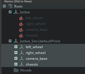
- If the moved prims appear grayed out (inactive), select them, right-click, and choose Activate to re-enable them
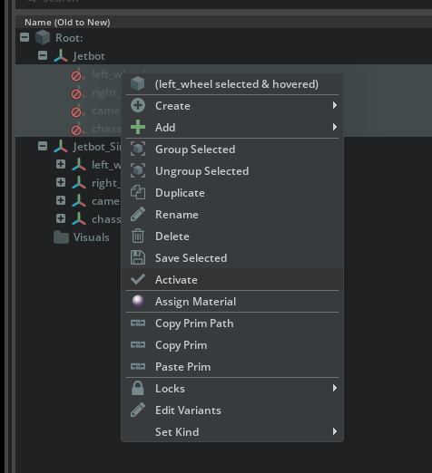
- Delete the meshes and materials that were copied under each
Jetbot_Sim/<link>(for exampleJetbot_Sim/left_wheel), but keep the link Xform itself. The link Xform serves as a container that will receive the merged mesh produced by the Mesh Merge Tool in the next step, so we leave the container in place and empty its contents.
Why empty the contents under Jetbot_Sim
The reparent operation also moves the children (meshes, materials, and so on) from Jetbot/<link> to Jetbot_Sim/<link>. These are still the unmerged originals; the next step uses the Mesh Merge Tool to produce a new merged mesh that replaces them, so we tidy them up here. The original mesh data remains in the Jetbot_base.usd sublayer (and under Jetbot/<original-link>), so the Mesh Merge Tool can still reference it as input.
Why prims become inactive
A prim "move" across USD sublayers is internally a deactivate at the source plus a redefinition at the destination. If the destination prim is inactive in the Stage panel, explicitly Activate it to enable it.
Step 2: Merge Meshes (Mesh Merge Tool)
Right after CAD import, a single Jetbot link is split into dozens of meshes and materials. Consolidating each link into a single mesh dramatically reduces both draw-call count and scenegraph prim count.
What the Mesh Merge Tool does
The Mesh Merge Tool combines multiple meshes into a single merged mesh and simultaneously consolidates their materials into a single combined material. The original meshes remain elsewhere, so they are still available for reuse if needed.
2-1. Open the Mesh Merge Tool
From the menu, click in the following order:
Tools > Robotics > Asset Editors > Mesh Merge Tool
The tool window opens.
2-2. Merge One Link (Left Wheel) End-to-End
Use left_wheel as the example to walk through the full merge flow:
- In the Stage panel, select
Jetbot/left_wheel - In the Mesh Merge Tool, check Combine Materials
- Set Material Save Location (the input field next to the Combine Materials checkbox) to
/Jetbot_Sim/Looks(the destination where merged materials will be collected) - Click the Merge button
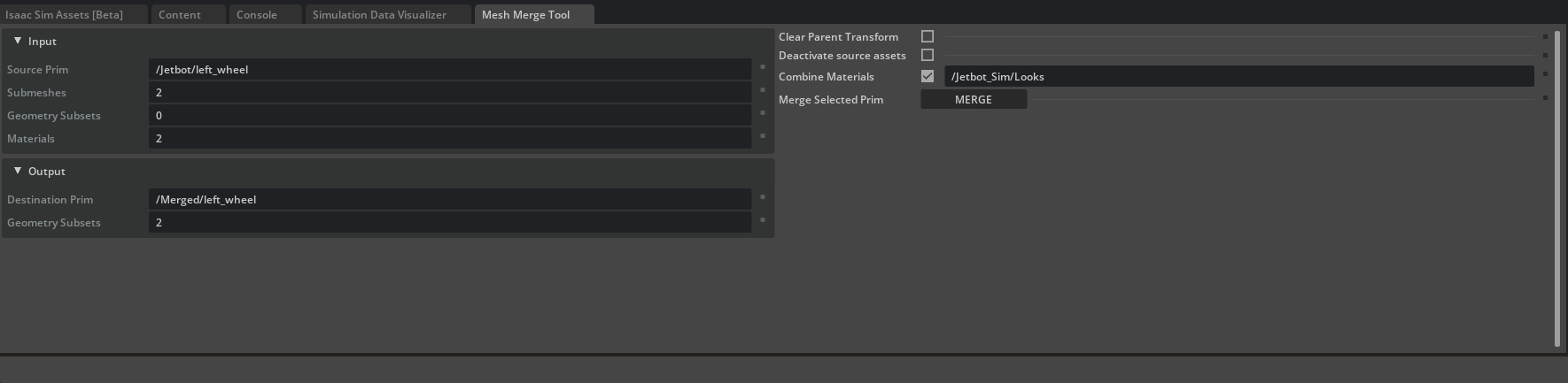
- The merged result is created temporarily at
/Merged/left_wheel - Select the new mesh and, in the Properties panel's Transform section, clear position, rotation, and scale to 0 (or identity values)
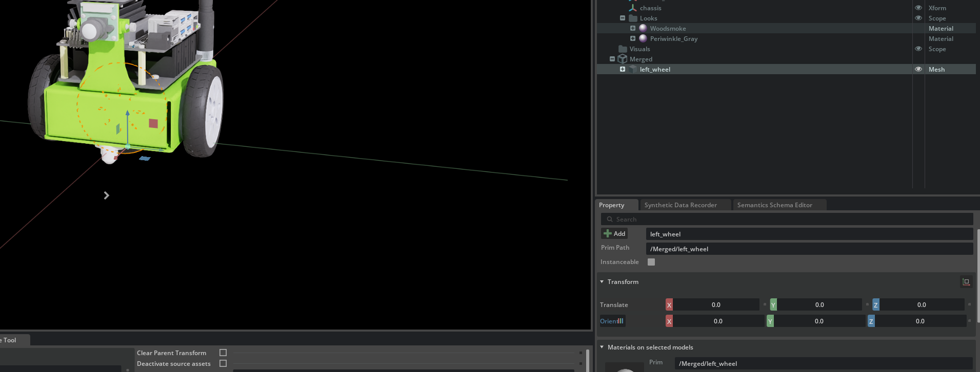
Why clear the Transform
The Mesh Merge Tool bakes the merged geometry relative to the selected prim's world coordinates. As a result, the new /Merged/left_wheel ends up with a Transform equal to its world position. If you then place this mesh under Visuals and reference it from elsewhere, leaving the Transform in place causes it to be applied twice (once at the source and once at the reference site).
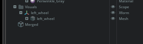
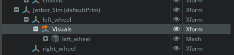
2-3. Build the Visual Reference Structure
Place the merged mesh under Visuals and have the simulation-side Jetbot_Sim/left_wheel access it via a Reference. This structure enables instancing in the next step.
- Create an Xform under
/Visualsand rename it toleft_wheel - Drag-and-drop
/Merged/left_wheelinto/Visuals/left_wheel - Delete the now-empty
/Mergedprim
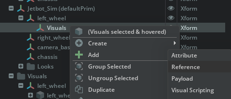
Next, add an Xform under the simulation-side link Jetbot_Sim/left_wheel that references Visuals/left_wheel:
- Under
Jetbot_Sim/left_wheel, create a new Xform and rename it toVisuals - Right-click the new Xform and choose Add > Reference
- In the file dialog, select the
Jetbot_base.usdyou copied to your working folder (the next step clears the Asset Path to convert this into an internal reference, so this file selection is just a temporary "stepping stone" to dismiss the dialog)
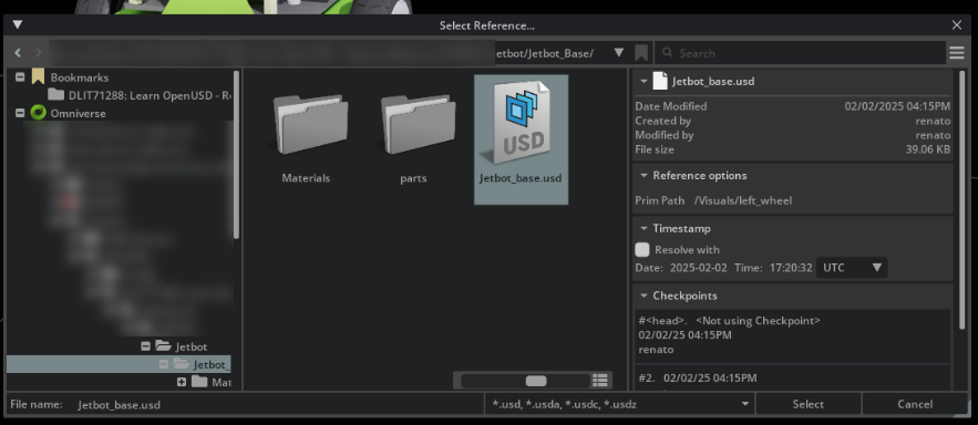
- In Prim Path, enter
/Visuals/left_wheel
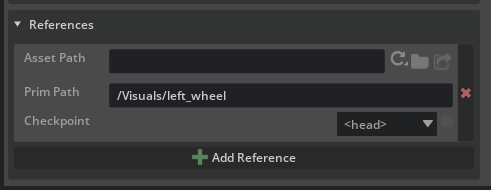
- In the Properties panel, expand the References section and clear the Asset Path value (this turns the reference into an "internal reference" that points within the same stage)
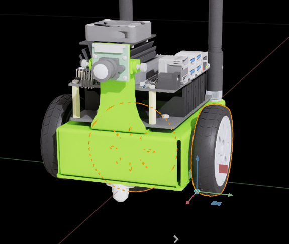
- Confirm that the left wheel renders correctly in the viewport and that the merged mesh appears under
Jetbot_Sim/left_wheel/Visualsin the Stage panel
Why use an internal reference
Storing the merged meshes under Visuals inside Jetbot_optimized.usd and referencing them from within the same file keeps the asset self-contained and free of external dependencies. The instancing step that follows is also applied to these internal references.
Reference vs Payload
As covered in Tutorial 10, References are always loaded, while Payloads support deferred loading (and can be Unloaded). Since the visuals are essential to the robot, we use References here.
2-4. Repeat for the Remaining Links
Apply the same flow to the other links such as right_wheel, chassis, and caster_wheel:
- Select
Jetbot/<link> - Use the Mesh Merge Tool's Merge button
- Clear the Transform on
/Merged/<link> - Move it to
/Visuals/<link> - Create an internal reference under
Jetbot_Sim/<link>/Visuals
Intermediate sample file
Merging every link is tedious, so Isaac Sim ships an intermediate file at Samples/Rigging/Jetbot/Jetbot_Optimized/Jetbot_optimized_post_merge.usd with merging already complete. To skip ahead and start from the instancing step, copy that file along with its related resources into your working folder before opening it (the Samples area is read-only, so opening it directly will not let you save).
Step 3: Scenegraph Instancing
The Jetbot's left and right wheels are identical in shape. Instead of holding two copies of the same mesh data, share a single data source for rendering to reduce both memory usage and rendering cost. This is scenegraph instancing.
What scenegraph instancing is
Instancing is a standard GPU mechanism for "drawing the same shape at different locations." In USD, setting Instanceable = true on a referenced prim lets Hydra (the USD render layer) collapse prims that come from the same source into a single draw call.
A trade-off to be aware of: child properties under an Instanceable prim cannot be overridden individually (so you cannot swap materials or transforms on a per-instance basis). Since we apply this only to visual meshes here, this restriction does not cause issues.
3-1. Consolidate the Common Geometry
Because the left and right wheels share the same geometry, consolidate the source under Visuals:
- Open the file you used in Step 2 (or the
Jetbot_optimized_post_merge.usdyou copied to your working folder) - Rename
/Visuals/left_wheelto/Visuals/wheel - Delete
/Visuals/right_wheel - Update the Prim Path in the References of
Jetbot_Sim/right_wheel/Visualsto/Visuals/wheel
Both Jetbot_Sim/<wheel>/Visuals now reference /Visuals/wheel.
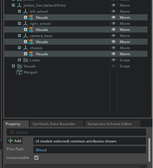
3-2. Enable Instanceable
Mark the referenced Visuals prims as instancing targets:
- Shift-click to select all
Visualsprims underJetbot_Sim(left_wheel/Visuals,right_wheel/Visuals,chassis/Visuals, and so on) - In the Properties panel, check Instanceable
- Verify that a blue "I" badge appears on the reference icons in the Stage
Instanceable and per-prim collider/material edits
Once Instanceable is enabled, you cannot change materials or collider approximations on a per-mesh basis under that prim. As covered in Steps 2-5 and 6-2 of Tutorial 10, if you need to swap materials per-link later, temporarily disable Instanceable on the target prim, make the change, and then re-enable it.
3-3. Cleanup Before Saving
Before you save, tidy up unused prims so the optimized asset is less confusing to use later. The original NVIDIA documentation also notes "you can hide the Visuals scope" — these steps are not strictly required but are recommended cleanup.
Hide the /Visuals scope
The meshes under /Visuals are displayed via internal references from Jetbot_Sim/<link>/Visuals. Because /Visuals itself also lives directly under root, leaving it visible can cause the base meshes to render twice in the viewport — once on the Jetbot_Sim side and once at /Visuals.
- In the Stage panel, select
/Visuals - Click the eye icon on the right of the panel to hide it (
visibility = invisible)
/Visuals itself is no longer drawn in the viewport, but it continues to function as a reference source, so the meshes shown via Jetbot_Sim/<link>/Visuals are unaffected.
Tidy up under /Jetbot
After the reparent in Step 1-5, /Jetbot no longer holds the link hierarchy. The exact appearance depends on USD composition behavior — its children may be grayed out, only empty Xforms may remain, or original meshes may still be visible. If the Stage panel feels cluttered, you can clean up using one of:
- Delete the
/Jetbotprim (a delete instruction is recorded in the Root Layer; theJetbot_base.usdsublayer is not modified) - Hide the
/Jetbotprim (toggle the eye icon)
Delete vs Hide
Delete removes /Jetbot from the composed result, giving the cleanest layout. As long as you have finished using /Jetbot/<original-link> as Mesh Merge input, deleting is fine. Hide is safer if you may want to re-reference one of those meshes later.
3-4. Save
After the cleanup, save the file with Ctrl + S.
Final-state sample file
Jetbot_optimized_final.usd represents the state after instancing is complete. Use it as a reference when you want to compare your end result.
Step 4: Other Performance Optimizations
Mesh merging and instancing are the two highest-impact techniques, but reviewing the items below can squeeze out additional FPS.
4-1. Rendering
Reduce the number of lights
Isaac Sim's default renderer switches to sample-based lighting once the scene has 10 or more lights, which sharply increases compute cost. Stick to the default environment light plus only the point lights you really need.
Avoid translucent materials
Translucent materials such as OmniPBR Translucent (glass, smoke, and similar) are noticeably more expensive than opaque OmniPBR and are common bottlenecks. Unless they are essential for a demo, prefer opaque materials.
4-2. Physics
Simplify collider shapes
A mesh collider (Triangle Mesh) is the most accurate, but switching to Convex Hull, Convex Decomposition, or basic primitives (Box / Sphere / Cylinder / Capsule) dramatically reduces physics cost.
| Collider | Compute cost | Use case |
|---|---|---|
| Box / Sphere / Cylinder | Low | Substitute for simple shapes (wheels, etc.) |
| Convex Hull | Medium | Balanced default |
| Convex Decomposition | Medium-High | Shapes with concavities |
| Triangle Mesh | High | Only when high accuracy is required |
Reduce the number of contact points
When multiple rigid bodies are in contact, the number of contact points dominates physics cost. Simplifying colliders also reduces contact points, so this item is closely tied to the previous one.
Use a cylinder or sphere instead of a mesh for wheels
Mesh colliders on wheels make ground-contact computation extremely heavy for mobile robots. Approximating a wheel with a Cylinder or Sphere improves both driving behavior and compute cost.
4-3. Make Measurement a Habit
Optimization gains depend on the environment and scene. Record FPS before and after each change so you can tell which steps actually paid off and avoid unnecessary work. Isaac Sim can show FPS in the HUD overlay, so check it after every optimization.
Troubleshooting
| Symptom | Cause | Resolution |
|---|---|---|
| World position shifts when dragging a prim | Inherit Parent Transform is disabled | Enable it under Edit > Preferences > Stage > Authoring |
| The destination prim is grayed out and not visible in the viewport | The cross-sublayer move deactivated it | Right-click the prim and choose Activate |
| Position shifts after Mesh Merge | Transform remains on /Merged/<link> |
Clear all values in Properties > Transform (position 0, rotation 0, scale 1) |
| No blue "I" badge on the reference even though Instanceable was enabled | The reference still points to an external file, or Instanceable is unchecked | Empty the Asset Path in References to make it internal, then enable Instanceable |
| Cannot edit per-mesh materials or colliders under an Instanceable prim | Instanceable is enabled | Temporarily disable Instanceable on the target Xform, then re-enable after editing |
| FPS does not change after optimization | Too many lights, leftover translucent materials, or mesh colliders still in use | Walk through the checklist in Step 4 |
| Base meshes appear twice | The /Visuals scope is still visible |
Hide /Visuals per Step 3-3 |
/Jetbot leftovers clutter the Stage panel |
The original asset hierarchy persists after the reparent | Hide or delete /Jetbot per Step 3-3 (the sublayer is not modified) |
Summary
This tutorial covered the following topics:
- Restructuring the asset — enable Inherit Parent Transform, then split into
Jetbot_Sim(link hierarchy) andVisuals(reference source location) - Mesh Merge Tool — consolidate per-link meshes and materials into a single mesh and material
- Visual separation via internal references — have the simulation links Reference
Visuals/<link> - Scenegraph instancing — share identical meshes from one data source by enabling Instanceable to lower rendering cost
- Other optimizations — review lights, translucent materials, colliders, and contact points
Combined, these changes take the Jetbot sample from 40 FPS to 64 FPS (about 1.6×). Mesh merging and instancing in particular tend to pay off well on real robot USD assets too, so they are a good first stop whenever simulation feels slow.
Also see the asset structure guidelines
The "base / optimized / features (physics, sensors)" separation introduced here follows the official Isaac Sim asset structure guidelines. Splitting layers by feature — physics, sensors, ROS, and so on — further improves reusability and maintainability.
Next Steps
Proceed to the next tutorial, "Rig a Legged Robot", to learn how to rig a legged robot for a locomotion policy.